Connections to the UDN (University Data Network) from an institutional network are typically made through a PoP (Point-of-Presence) switch, physically located on the client site. ISPs typically call this CPE (Customer Premises Equipment).
The PoP switch provides an interface between the UDN backbone and the client institution, presenting the UDN services in a form appropriate to that institution (e.g. which physical ports have which VLANs tagged and untagged).
This page describes the PoP switch hardware and software configuration, as well as the other equipment installed at the client site.
Institutions can choose to connect without a PoP switch using the BGP service.
Contents
- Client site equipment
- PoP switch connections
- Institutional connection configuration
- Spanning Tree
- Pinging the PoP switch
- Miscellaneous PoP configuration settings
- Services available on the PoP
- Split PoP
- Maintenance of the PoP equipment
- Prices
Client site equipment
In most cases, one or two pieces of equipment are installed as part of a UDN connection (in addition to any cabinets or fibre termination):
- PoP switch
- Uninterruptible Power Supply (UPS) (optional)
This equipment is described below.
PoP switch
There are three main models of PoP switch available, all from Cisco Systems: the Catalyst 3850, Catalyst 9300 and Catalyst 9500, all taking up 1U of rack space:
| Option | Model | Institution downlink ports | UDN uplink ports | Notes |
|---|---|---|---|---|
| 1G-24C | C3850-24P + C3850-NM-4-1G |
20x 10M/100M/1G RJ45 w/ PoE+ 2x 1G SFP |
2x 1G | |
| 10G-4 | C3850-48P + C3850-NM-4-10G |
44x 10M/100M/1G RJ45 w/ PoE+ 2x 1G/10G SFP+ |
2x 10G | No longer available |
| 10G-12 | C3850-12XS | 10x 1G/10G SFP+ | 2x 10G | Replaced by C9500-16X model |
| C9500-16X | 14x 1G/10G SFP+ | 2x 10G | Retains the 12-port pricing of the previous offering | |
| 10G-24 | C3850-24XS | 22x 1G/10G SFP+ | 2x 10G | Replaced by C9500-24Y4C model |
| C9500-24Y4C | 22x 1G/10G/25G SFP+ | 2x 10G | ||
| S10G-12 | 2x C3850-12XS | 14x (= 2 switches x 7x) 1G/10G SFP+ | 2x 10G (= 1x from each switch) | Replaced by C9500-16X model |
| 2x C9500-16X | 22x (= 2 switches x 11x) 1G/10G SFP+ | 2x 10G (= 1x from each switch) |
Below is a table giving the prices of the various options.
The 1G-24C option is largely analogous to the previous generation PoP switches, the Cisco Catalyst 3560G-24PS, installed in 2008. The other options are for institutions requiring a 10GE connection to the UDN backbone:
- (Deprecated.) The 10G-4 option provides 44x RJ45 copper ports with PoE+ for institutions who wish to retain some copper edge device connectivity on the PoP, as well as 2x 1G/10G SFP+ downlinks to an institutional network. Note that, due to technical limitations of the Catalyst 3850 range, this needs to be a 48-port switch to support the 4x 10G module required to provide 2x 10G uplinks and 2x 10G downlinks.
- The 10G-12 and 10G-24 options provide 10x and 22x 1/10G SFP+ downlinks respectively, to institutional switches, allowing it to be used as an aggregation switch for the core of an institutional network.
- The S10G-12 option provides 2x 7x (7 per switch) 1G/10G downlinks, using two switches that can be located in physically separate locations, interconnected by 3 fibre links. This is described in more detail below.
All options are supplied with two hot-swappable, redundant power supplies, eliminating the need for the separate Redundant Power Supply (RPS) unit supplied with the previous Catalyst 3560G PoP switches. Power will seamlessly fail back and forth between units, without interruption. It is recommended that institutions notify UIS Networks that they perform maintenance on the power feeds to avoid an interruption being suspected as a sign of impending equipment failure, but a short outage during a likely maintenance window will typically be ignored.
The switches featuring copper ports (1G-24C + 10G-4) are supplied with a 715WAC power supply, providing a total of 435W PoE. All ports are capable of supplying PoE+ power, up to that maximum.
Uninterruptible Power Supply (UPS)
If the switch is required to continue to run in the event of a mains power failure, it is recommended that one of the two power supply inputs is attached to an Uninterruptible Power Supply (UPS) and the other to a separate feed (most likely the mains): it is not recommended that both supplies are connected to the same source, even if it is a UPS, as this can suffer issues or require maintenance which will affect both supplies.
The UIS no longer supplies UPSs for PoP switches — institutions requiring power protection for their PoP must source and maintain the UPS themselves. The maximum load required from the UPS will depend on the PoP model and number of PoE devices attached but will typically be around 1000VA.
PoP switch connections
All PoP switches require 2 fibre ports for use as the UDN uplink.
Fibre PoPs leave all the remaining ports available for institutional downlinks; the split 10G PoPs leave 7 ports for institutional downlinks on each unit.
On a copper PoP switch (1G-24C and 10G-4), 4 ports are reserved for UDN use, leaving 20 or 44 (depending on the option) available to an institution:
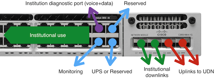
The ports are designated as follows:
| Port(s) | Assigned to | Purpose | ||||
|---|---|---|---|---|---|---|
|
1G-24C |
10G-4 |
10G-12 |
10G-24 |
S10G-12 |
||
|
1-20 |
1-44 |
SFP+ |
SFP+ 1-22 |
SFP+ 1-7 |
Institution | Institutional downlinks |
| 21 | 45 | - | Institution | Diagnostic port | ||
| 22 | 46 | - | UIS | Monitoring port | ||
| 23 | 47 | - | SFP+ 11 |
UIS | Reserved port | |
| 24 | 48 | - | UIS | UPS management port | ||
| - | - | - | SFP+ 8-10 |
UIS | Split PoP interconnects | |
| SFP 3+4 |
SFP+ 3+4 |
SFP+ 11+12 |
SFP+ 12 |
UIS | UDN uplink ports | |
The 16-port replacements for the 10G-12 and S10G-12 services will have 4 additional institutional downlink ports and the ports used by the UDN (and interconnects, for the S10G-12 model) will shuffle along by 4 ports to the end.
Institutional downlink ports (copper and fibre)
Downlink ports are available for the connection of any devices the institution requires. These can be edge devices (e.g. phones, computers, wireless APs) or network devices (e.g. internal switches, firewalls, routers). Essentially, the institution can request any configuration of the available ports (with appropriate VLANs, PoE, QoS, etc.) it desires. For copper PoPs, it is recommended that ports 1-12 (1G-24C) / 1-36 (10G-4) are used for the connection of edge devices and ports 13-20 / 37-44 are used for connections to network equipment. It is understood that this might not be appropriate in all cases.
SFP/SFP+ downlink ports can be ports can be used the same as the above copper ports — institutions can either use their own Cisco-compatible transceiver(s) or rent one with the PoP. If the institution provides the transceiver, it is responsible for holding spares and carrying out fault investigations (including replacing it, if it is suspected faulty), as well as replacing it, if the PoP hardware changes and the previous model is incompatible. SFP+ ports can be used with Direct Attach Cables (DACs).
For more information on how these ports can be set up, see institutional connection configuration, below.
Diagnostic port
It is recommended institutions keep port 21 (1G-24C) / 45 (10G-4) free for the temporary connection of diagnostic equipment (e.g. a voice handset or test host). Essentially, this port just has the main institutional VLAN untagged and the institutional voice VLAN tagged and advertised with CDP/LLDP-MED so two devices (or daisy-chained phone and PC) can be attached.
These ports are useful, in the event of a network fault, to perform tests from outside an institution's network and confirm if the fault is from the PoP upwards to the UDN. If these ports are used for the permanent connection of devices, an available test point is removed and can make diagnostics more difficult. Note that the port profile is that of an edge port, so only a single device should be connected.
Monitoring port
When diagnosing faults, it can be useful to direct a copy of the network traffic to a probe to analyse it. Sometimes this can be done remotely but, occasionally (as with many Quality of Service [QoS] problems) it can be useful to install a traffic capture probe on-site. Port 22 (1G-24C) / 46 (10G-4) provides a location where such a probe can be attached and a copy of the relevant network traffic directed.
This port is for the attachment of a probe by UIS Networks. If institutions wish to do this for their own use, one of the institutional downlink ports can be used, with a separate monitoring configuration.
Reserved port
Port 23 (1G-24C) and 47 (10G-4) is reserved for either temporary diagnostic or other purposes by UIS Networks.
On other PoPs, it is recommended that a port is left free for UIS purposes, otherwise parts of the internal network may need to be disconnected to investigate a fault.
UPS management port
If the institution has a managed UPS attached, the cable to the management card of the Uninterruptible Power Supply will be attached to port 24 (1G-24C) or 48 (10G-4), enabling the UPS to be monitored and controlled.
UDN uplink ports
PoP switches have two connections to the UDN backbone for redundancy. These will go to different UDN backbone routers to help remove the impact of a single backbone device failing and, where possible, will take diverse physical routes across the GBN (Granta Backbone Network).
Redundancy on routed VLANs will be handled by a First Hop Redundancy Protocol such as VRRP or HSRP. Switched VLANs (e.g. the UDN 'VLAN Service') will be redundantly handled across the backbone to the corresponding destination PoPs. Institutions should not need to perform any reconfiguration or notice any outage, other than a brief (maximum 3 seconds, in the case of routed VLANs) interruption while backup connections take over
Institutional connection configuration
There are four main ways in which the institutional downlink ports can be configured. These affect parameters other than just the VLANs, including Quality of Service, Spanning Tree and CDP (Cisco Discovery Protocol).
The different configurations between these port types are summarised below:
| Port type | ||||
|---|---|---|---|---|
| Edge | ATA-24 | Wireless AP | Trunk | |
| Purpose | A single device - computer, phone, 2-port ATA (e.g. Cisco ATA-186) or computer/phone daisy-chained); mini-hubs/switches over 4 ports should not be attached (a Trunk port should be used here). | 24-port analogue telephony adapter (e.g. Cisco VG224). | Direct connection of a single University Wireless Service access point (multiple APs attached to a downstream switch should use a Trunk port). | An institutional network, either entire or part, with multiple downstream devices (computers, phones, wireless access points, etc.); this would be connected to a switch, firewall or other networking device. |
| VLANs | Optional untagged ('access') and optional tagged voice VLAN | Untagged VLAN (voice) | One untagged (for AP management) and, if required, one or more local institutional VLANs tagged | Optional untagged ('trunk native') and any number tagged ('trunk') |
| Cisco switchport mode | Access | Trunk | ||
| Spanning Tree | Enabled with 'portfast [trunk]' and 'root guard' | Enabled | ||
| VoIP QoS profile | Single phone (128kbit/s payload, 32kbit/s signalling) | Up to 24 phones (3Mbit/s payload, 768kbit/s signalling) | Many (>1000) phones (64Mbit/s payload, 10Mbit/s signalling) | |
| MAC address limit | 20 addresses, 15 minute aging upon inactivity | None | ||
| PoE | Enabled | Disabled | ||
| CDP | Enabled | Disabled | ||
| LLDP / MED Policy TLV | Enabled / Enabled | Enabled / Disabled | ||
| DHCP Snooping | Untrusted, limit 15pps | Trusted, limit 2000pps | ||
| ARP Inspection | Trusted, limit 15pps | Untrusted, limit 15pps | Trusted, limit 2000pps | |
It is important to use the appropriate type of connection for the device being connected to a particular port: using the wrong type of port configuration may appear to work at first but present problems later (e.g. issues with Spanning Tree or QoS thresholds). It is also possible additional features may be enabled in future that will cause a port being used in an incorrect way to stop working; if in doubt, please contact UIS Networks for advice.
Ports can be reconfigured by contacting UIS Networks. Note that unconfigured ports will typically be shutdown/disabled but this should not be relied upon. If asking for a port to be reconfigured that is physically up, it is best to confirm this, when contacting the UIS, to avoid additional delay while we make sure the wrong port number has not been given (and reconfigure an active device).
Spanning Tree
An important change from the previous PoP configuration is that Cisco Rapid-PVST+ Spanning Tree is now configured on institutional downlink trunk ports (it has always been configured on edge ports, however).
Previously, Spanning Tree was disabled on those ports, using the "BPDU Filter" and "Portfast Trunk" settings. The first of these settings blocks the sending and receiving of Spanning Tree BPDUs (Bridge Protocol Data Units — the frames which are used to exchange Spanning Tree information between switches), preventing interaction between the PoP and institutional switches using the Spanning Tree Protocol. The second setting causes the port to move immediately into the forwarding state, rather than waiting 30s to see if there is an adjacent switch speaking Spanning Tree and check for a loop or other topology change (which would not be detected anyway, since BPDUs are filtered out) .
The new configuration has these settings removed. These result in the following changes:
- If the attached switch does NOT speak Cisco Rapid-PVST+ (i.e. it speaks a version of IEEE spanning tree, or no spanning tree protocol at all), a trunk port will take 30s to move into the forwarding state, when a link is brought up.
- If IEEE protocols are used by the institutional switches, the Spanning Trees will not interact and redundant topologies involving the PoP cannot be built: the effect is as if the other side of the network does not have Spanning Tree configured. Note, however, that BPDUs can flow through the VLANs on either side as they will usually be ignored by switches running a different protocol; this can have odd effects, as Spanning Trees or VLANs can be joined unexpectedly.
- If the attached switch DOES speak Cisco Rapid-PVST+, the switchport mode and trunk native VLAN must match those presented on the PoP. For example, if VLAN 789 is presented on the PoP as trunk native / untagged, but the institution is using a different number, e.g. VLAN 1, also configured trunk native / untagged, the port will block due to a VLAN ID mismatch. Likewise, the port would also block if the institution end is configured as an access mode port, even if the VLAN ID matches.
Incompatibilities between VLAN IDs can often be worked around by filtering Spanning Tree BPDUs at the institutional end, but these can also prevent genuine problems from being detected and result in wider outages. It is strongly recommended that the institutional network is configured to match the VLANs and modes of the PoP.
In addition to the above changes, root guard (where the PoP would block a port where the root bridge role appears) is NOT configured on trunk ports, allowing institutions to move the root bridge for a VLAN inside their network. These changes allow institutions to build redundant topologies involving the PoP switch, including redundant uplinks. The UDN will use priorities of 16384 and numerically higher (i.e. lower in effective priority); institutions wishing to take over the root bridge role must configure a priority numerically lower than 16384 (i.e. 4096, 8192 or 12384).
The backup port service offered on the previous PoPs is no longer available on the new PoPs. It is recommended that institutions move to use spanning tree or port channels, as a mechanism to build a redundant topology involving the PoP. This can be combined with the split PoP service to build a fully redundant connection with the PoP.
Institutions must verify the configuration of their internal network and how it interconnects with the PoP to understand the implications of these changes and make any preparatory changes in advance, or at the point where the connections are moved across to the new PoP. Despite Rapid-PVST+ being a Cisco proprietary protocol, many other vendors support this protocol, although it is unlikely to be configured as the default.
It is recommended institutions enable Rapid-PVST+ and ensure their VLAN and port configurations match those on the PoP, as this will give the best interoperability with the UDN. Running alternative protocols is supported but institutions must understand the limitations and side effects of a mixed configuration.
Requesting reconfiguration of the PoP
When an institution wishes for a port on the PoP to be changed to a different type (e.g. edge to trunk) or a change in the VLANs presented, they should contact Information Services with the following information:
- the [institutional downlink] port number, or a range of numbers
- the type of port required (edge, ATA-24, wireless AP, trunk)
- for edge ports:
- the untagged/access VLAN to be used (if required)
- if the voice VLAN is to be served tagged, via CDP/LLDP-MED
- for trunk ports:
- which VLAN is to be untagged/native (if any)
- which VLAN(s) is/are to be tagged/trunk (if any)
Note that untagged VLANs lose their 802.1p CoS (Class of Service) information, which may affect the ability of other some other network devices to determine the appropriate Quality of Service. Note that the UDN uses DSCP (DiffServ) to determine QoS, and will set the 802.1p value based on this, so will not be affected by this.
Recommendations for PoP switch port configuration
Whilst any arrangement of ports of different type and VLAN is available, it is strongly recommended that ports configured similarly are physically grouped on the switch. For example, if there are two voice downlinks to separate switches, they use physically adjacent ports.
Also, while it is possible to use untagged VLAN presentation as a way to feed a VLAN into an institutional network and retag it, this can result in the wrong VLANs being interconnected, if a mistake is made. Using institutional VLAN IDs that match the UDN VLAN numbering system and tagged connections minimises the chances of this happening.
When VLANs on a particular port are no longer required, or a port is not needed any more, it is recommended they are unconfigured by contacting UIS Networks. Not doing this can result in traffic passing down links unexpectedly (perhaps affecting Quality of Service or traffic levels in general), new devices being temporarily connected to the wrong VLANs or undetected loops causing packet storms.
Finally, while ports can be given fixed speed or duplex settings, it is recommended they remain left to autonegotiate these parameters. Disabling autonegotiation can also affect other link parameters and increases the potential for mismatched settings. Most network devices now correctly autonegotiate link settings over both fibre and copper interfaces; the odd exception is often fibre-to-copper media converters.
Pinging the PoP switch
The status of the PoP switch can be checked by using the PING utility. Note, however, that the IP addresses of PoP switches are on special 'management VLANs' that are separate from the institutional VLANs. As such, traffic to and from them must be relayed through the upstream UDN router; just because the PoP is not responding might not mean that it is not operational but the upstream connection is broken in some way and traffic cannot be routed between the two VLANs.
The UDN Network Status page also lists each institution's PoP and its operational status. The names of the PoPs are of the form pop-<inst>.net.private.cam.ac.uk (or, for option 4, spop-<inst>.net.private.cam.ac.uk; the 's' standing for 'split') where <inst> usually corresponds to an institution's domain name under cam.ac.uk, possibly followed by a site identifier, where an institution has multiple PoPs. The name should also be shown on the identification label on the front.
Miscellaneous PoP configuration settings
A number of global settings are configured on the PoP switch to protect the network and improve reliability. These settings should not have any effect on the network during normal operation but are described here for reference.
Storm control
To avoid broadcast storms flooding the network and consuming bandwidth away from other traffic, all interfaces (regardless of type) have a limit on ingress of broadcast traffic of 5% of total operational bandwidth (e.g. for a 1Gbit/s interface, a maximum of 50Mbit/s). Traffic over this limit will be dropped; non-broadcast traffic (unicast or multicast) will continue to be forwarded.
This level has been chosen as it is very unlikely that the normal operation of the network will require this amount of broadcast traffic; situations where this is exceeded are most likely to be loops or problematic clients. The switch records an event in its internal log that this has happened.
DHCP Snooping / ARP Inspection
To improve the reliability and security of the network, DHCP Snooping and ARP Inspection are enabled on all VLANs fed into the institutional network. These two features validate DHCP and ARP traffic to make it harder for rogue devices to affect the operation of the network:
- DHCP Snooping prevents rogue DHCP servers from operating on switch ports which are not nominated as trusted by blocking packets from servers being received, or packets to servers from being transmitted on those ports. In addition, the DHCP traffic flowing through the switch is snooped to build a binding database of MAC/IP/interface mappings for hosts on untrusted ports.
- ARP Inspection uses the binding database built by DHCP Snooping to block ARP packets advertising MAC/IP mappings which do not match those issued by the DHCP server, unless the port on which they are received is nominated as trusted.
The rationale behind the configuration of the ports on a PoP switch is that DHCP servers are usually either inside the institutional network or upstream on the UDN, so edge ports are untrusted for DHCP Snooping. However, many institutions do not rely on DHCP to configure client addresses exclusively (rather than static configuration) so the PoP cannot filter ARP packets and must treat all ports as trusted, unless they have devices which are known to be managed by DHCP from the UDN (such as wireless APs or ATAs).
In addition to the above functions, the features also rate limit these packets as an excessive number of them can have a serious detrimental effect on the operation of the upstream router. if these limits are hit, the PoP switch will drop packets randomly, to stay under it. This can prevent devices from being able to work reliably, until the rate of packets is reduced below the configured limit.
It is strongly recommended that institutions deploy these features internally, according to local policy, and mitigate these problems before they reach the PoP, where the effect of the packet drops will be more widespread.
MAC address limit on edge ports
As stated above, edge and ATA-24 ports have a limit of 5 MAC addresses with a 15 minute inactivity timer. This helps prevent problems caused by devices with faulty network interface adapters emitting many different, and invalid, MAC addresses and filling the internal switch MAC address forwarding table, causing flooding of traffic.
This value was chosen as a sensible limit for a port with a computer and phone, possibly with a small number of desktop VMs (Virtual Machines) leaving some spare addresses for additional MAC addresses on virtual machines (for example). If the limit is reached, an event is recorded in the switch's log and the additional addresses not learnt.
If multiple devices are to be attached to an interface on the PoP switch, it is important to ensure that interface is configured as a trunk type, regardless of whether a large, rackmount switch or desktop mini-switch is used.
Services available on the PoP
Aside from the client configurations listed above, a number of additional services can be enabled on the PoP switch upon request.
Institutional monitoring
If an institution wishes to monitor traffic passing through the PoP, they can request that one or more of the downlink ports is configured as a monitoring destination, monitoring one or more other downlink ports. This can either be as a temporary measure, to investigate a specific current problem, or as a more permanent installation to log inbound/outbound traffic.
If the institution requires this service, it should contact UIS Networks with the parameters for the traffic to be captured:
- the destination [downlink] port to receive the monitored traffic
- the source [downlink] port(s) whose traffic is to be copied to the monitor port (this can be 'all')
- the VLAN(s) to be monitored (this can be 'all VLANs')
- whether inbound, outbound or both directions are to be captured
The institution cannot request monitoring of VLANs or ports used by the UDN itself (e.g. the uplink ports or the management VLANs). It should also be noted that monitoring multiple ports or a full-duplex link may result in more traffic being copied to the monitor port than can be handled by it (e.g. a full-duplex 1Gbit/s link is capable of carrying up to 2Gbit/s) - in this case, traffic will be discarded by the monitor port.
Link Aggregation Groups (portchannels, trunks, etc.)
To increase the bandwidth of logical links, the PoP switches support the configuration of Link Aggregation Groups (LAGs), also called portchannels [Cisco], trunks [HPE ProCurve, not to be confused with Cisco switchport trunks] or sharing groups [Extreme]. These allow multiple physical links to be aggregated together into a single logical link. As the links to the UDN backbone are both active, a 1G PoP can potentially receive up to 2x 1Gbit/s of traffic, saturating a single downlink port.
Typically, the LAG is managed using the LACP protocol with slow LACPDUs (LACP Data Units, the frames which control LACP). LACP allows switches at both ends to negotiate to ensure that all the ports are in the same group and can be aggregated successfully; if not, the links which cannot be aggregated will be deselected (not used). This helps avoid misconfigurations either at the software level, or with the physical cabling.
This service is particularly useful on the split PoP as ports can be aggregated across the two switches into a single link, allowing an active-active, physically redundant topology, assuming the institutional equipment supports a similar configuration.
It should be noted that LAGs will usually hash the traffic to distribute it across the members, resulting in individual flows being pinned to a particular pair of ports (which can be different in each direction). If there are a large number of smaller flows passing across the LAG, this usually will distribute the traffic fairly evenly. If the network has a small number (or one) very intensive flow, however, these can sometimes be hashed to same interface pair(s) and result in usage of the links being uneven. As such, it is recommended that, if traffic levels are routinely exceeding that of individual links, a faster link speed is considered (e.g. 10GE over 1GE).
Local VLAN Service
If an institution requires a VLAN to be kept locally within a site but fed through the PoP (e.g. an 'internal' VLAN behind a firewall they want fed back through the PoP to be served as an untagged/access VLAN on phones attached to the PoP, or another switch attached to a separate port on the PoP), it can request this.
There is no charge for this service but:
- the VLAN 802.1Q tag will come from from the range 4000-4094 ("Local" in the UDN VLAN number allocation system, but note that it excludes other VLAN tags <4000 that are also classed as Local — this is because those tags are used by the UDN internally)
- the VLAN cannot pass onto the UDN core
The institution should contact the UIS stating which ports on the PoP switch the VLAN is desired on and whether it should be tagged or untagged.
If a VLAN is required elsewhere on the UDN, the full (chargeable) UDN VLAN Service can be ordered from the UIS and the tag will be allocated from the Global set.
UDN VLAN Service and Q-in-Q tunneling
If an institution requires a VLAN to cross the UDN, it can request the UDN VLAN Service with optional Q-in-Q tunnelling.
SNMP monitoring
If an institution wishes to monitor the PoP switch for status or statistics, read-only SNMP access can set up to allow this. Requests should be made to the UIS stating:
- the desired community string (which cannot be 'public', 'private' or any names reserved by the UIS)
- an institutional address (or network/mask) from which queries will be sent
Access will be granted to the standard system and interfaces areas of the MIB (Management Information Base). It should be noted that the PoP switches reside on special 'management' VLANs which are separate from the normal institutional VLANs so requests will be relayed through an upstream UDN router and will not be available if that connection is unavailable.
Split PoP
The Split PoP (S10G-12) service gives institutions a pair of switches, typically installed in physically separate locations, that are configured to operate as a single logical switch from the point of view of spanning tree and other services. In particular, LACP port channels can be created across both switches, to present a single logical link. If an institution has a similar feature on their own switches, they can form a physically redundant topology that doesn't rely on spanning tree and is active-active.
This solution results in many of the benefits of the BGP service but without the institution needing to undertake the overhead of running BGP and the associated costs of equipment and staff resource.
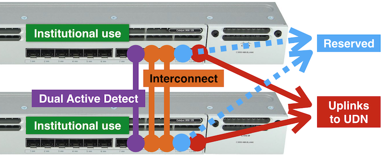
Here, two 10G SFP+ PoP switches, of the same model as 12x 10G SFP+ PoP (10G-12), are installed and interconnected via three fibre links:
- 2x 10G links form the StackWise Virtual interconnect — this is the link which allows the two switches synchronise configuration and runtime information
- 1x 1G link is used as the Dual Active Detect — a link which, if both of the StackWise Virtual interconnects fail (or there's an operational problem with the link) is used to prevent both switches becoming active independently
The interconnects between the two switches should take physically diverse paths, where possible. If all of these links fail, the switches will go active independently and cause connectivity problems, essentially breaking the connection. These links can use GBN and/or institution-owned fibre (either singlemode or multimode, although note that the StackWise Virtual interconnects must run at 10Gbit/s). The UIS will typically plan and order these on behalf of the institution, but will discuss with them, if there are any specific requirements. If the interconnects involve GBN circuits, these will be recharged at cost.
This functionality requires some hardware capabilities present in the Catalyst 3850-12XS not present in the 1G models (including the Catalyst 3850-24P and 3850-48P). As such, it is not possible to offer this service on a 1G UDN PoP option.
Software upgrade process on Split PoPs
At the present time, software upgrades on split PoPs cannot be scheduled outside hours and must be manually initiated by the UIS. The entire process takes between 25 and 40 minutes and involves the following stages:
- The secondary unit prepares and installs the new software release. (This typically takes between 5-10 minutes.)
- Once installed, the secondary will restart onto the new software. During the restart, links on the secondary will go down, along with the UDN uplink from it, but any links on the primary will continue to work as normal. (10-15 minutes.)
- When the secondary unit has restarted, the virtual stack is re-formed and the links will be brought back online.
- The primary unit prepares and installs the new software release. This will take a few minutes.
- Once installed, the primary will restart onto the new software. During the restart, links on the primary will go down, along with the UDN uplink from it, but any links on the secondary will continue to work as normal. (10-15 minutes.)
- When the primary has restarted, the virtual switch is re-formed and the links will be brought back online.
For ports that are a member of a LAG, the peer switch will just see that port go down and then be re-added a few minutes later, as the switch restarts.
It is not possible to pause this process or state exactly the time each point in the process will occur as sequence is automated. The timings given above are approximate and can vary between releases or due to other issues.
The UIS can advise which switches are the active primary and secondary before the process but it should not matter in practice. The primary is not necessarily the 'first' switch in the virtual stack.
It is the responsibility of institutions to design their networks to support graceful failover during this sequence, either through redundant uplinks or LAGs: the entire purpose of having a split PoP is to build a network that continues in the event of a fault or maintenance.
Maintenance of the PoP equipment
The UIS will, from time to time, make changes to the PoP switch software and configuration to maintain its operation, keep up to date with security and resolve problems. In most cases, these can be made without affecting service to the client institution. However, if downtime is required (e.g. an operating code update), the client institution will be given suitable warning and this will happen during an appropriate "at risk" period, where possible.
In the event of a hardware fault or other situation where the PoP equipment needs to be physically accessed, the UIS will need to visit the site and carry out the appropriate work. For this reason it is requested that:
- items are not placed on top of the PoP, making removal or access difficult
- cables between other devices in the same cabinet that hang in front of the PoP can be moved out of the way, enabling the PoP to be removed without affecting other connections
- cables connected to the PoP use different colours or identifying labels to indicate different configurations (port type and VLAN[s]), making it easier to identify the cables, if the equipment is swapped
- access to the rear of the switch is maintained, especially for the connection of a serial console cable for out of band access
- the PoP cabinet area is kept clean and generally tidy
Failure to observe these guidelines may render the UIS unable to perform the desired maintenance or cause it to take excessive time.
Prices
The PoP switch incurs an installation cost and an annual charge:
| Service |
Annual Charge |
New Installation |
Crossgrade Installation |
|---|---|---|---|
|
1G-24C (24x RJ45 + 4x SFP) |
£2,959 | £13,331 | £5,022 |
|
10G-4 (48x RJ45 + 4x SFP+) |
£5,072 | No longer available | No longer available |
|
10G-12 (12x SFP+) |
£5,465 | £19,777 | £11,467 |
|
10G-24 (24x SFP+) |
£5,835 | £22,370 | £14,061 |
|
S10G-12 (Split 2x 12x SFP+) |
£7,260 |
£30,859 |
£22,550 |
|
PoP relocation |
- |
£2,075 |
|
All charges are subject to VAT, where applicable. Prices last updated 13th November 2024.
The prices include the initial purchase, setup and upgrade of the equipment, as well as the GBN circuits to the upstream UDN routers. They do not cover GBN circuits between halves of a split PoP. They also cover any associated work triggered by the UIS (e.g. the replacement of equipment due to upgrades or failures).
The "crossgrade installation" is to change from one service to another, without moving the equipment or GBN circuits — the installation charge is reduced to just include the purchase of the new equipment and the labour required to configure and install it.
Last modified: 26th June 2024