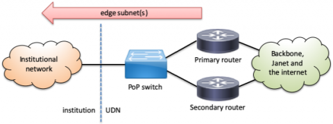
An institution connects to the University Data Network (UDN) physically through one or more interfaces on its PoP switch, or via direct links to UDN routers running BGP. Logically, it does it through one or more VLANs which carry the IP subnets used by the institution, either directly, or as a routed link between the UDN router and the institutional router.
This page describes how these VLANs and subnets are configured, including how redundant routing is configured. The content of this page is of a technical nature and a good understanding of TCP/IP is required to understand some of details; the intended audience is institutional network managers.
Contents
- Connection models
- Redundant connections
- Services available on edge connections
- Hostnames for router addresses
Connection models
The IP configuration on the institutional VLAN presented on the PoP switch typically follows one of two models:
- edge - the VLAN provides a direct connection for edge devices (e.g. computers, printers, etc.), perhaps with a proxy ARP firewall, or
- routed link - the VLAN provides a routed connection between an institutional router or firewall and the upstream UDN router.
In practice, the configuration can be a hybrid of these models but care must taken by the local network manager to ensure traffic is routed correctly. The two models are described below.
Most institutions have all of their IP addresses delivered across a single VLAN, but they can request that their routed IP service be split across multiple VLANs (in addition to any service VLANs for devices such as VoIP telephones or University Wireless Service access points). This is the additional routed VLAN service and is described separately.
It should be noted that a VLAN/subnet is only routed to a single PoP switch and cannot be extended to other sites. Traffic between sites will be routed across the UDN backbone.
Edge connections
The most common and simplest type of connection has the IP subnet(s) used by the institution presented directly on the VLAN served by the UDN router(s). The VLAN is usually taken from the PoP and carried through the institutional network directly to the edge ports serving networked client devices such as computers and printers. The subnet(s) can be global and/or UDN-local, including a mix of the two types.
This type of connection is also used with proxy ARP firewalls as the outside or untrusted VLAN. The firewall responds to the UDN routers on behalf of client devices and selectively permits or denies traffic between this outside VLAN and an internal institutional inside or trusted VLAN where the client devices are connected. To the UDN routers, it appears that the client devices are directly connected to the outside VLAN and do not need any special configuration to route traffic through the firewall.
UDN edge address organisation
For subnets routed directly by the UDN, some of the addresses are reserved for UDN use. Which addresses are reserved for the router(s) depends on the size of the subnet and when the allocation was made; the table below summarises the different schemes in use (the scheme names are internal terms to refer to the layout). Some of the schemes shown here are used on routed links and not on regular edge subnets, but are shown here for completeness).
| Scheme | Default gateway | Primary router | Secondary router | Available to institution | Comments |
|---|---|---|---|---|---|
| "62" | base + 62 | top - 1 | base + 61 | base + 1 → base + 60 base + 63 → top - 2 |
Default prior to May 2008. |
| "62-alt" | base + 62 | top - 1 | top - 2 | base + 1 → base + 61 base + 63 → top - 3 |
Useful when base + 61 has already been used by the institution. |
| "top" | top - 1 | top - 2 | top - 3 | base + 1 → top - 4 | Default since May 2008; also corresponds to routed link arrangement. |
| "bottop" | base + 1 | top - 1 | top - 2 | base + 2 → top - 3 | Special arrangement for legacy routed links. |
| "bottom" | base + 1 | base + 2 | base + 3 | base + 4 → top - 1 | Special arrangement for some routed links. |
| "254" | base + 254 | base + 253 | base + 252 | base + 1 → base + 251 base + 255 → top - 1 |
Special arrangement for enlarged subnets using the top scheme. |
The remaining addresses are usually available for institutional use although this should be confirmed in the appropriate IP registry (e.g. UIS Networks). Note that the UDN PoP equipment (switch and UPS) do not reside on institutional subnets but on separate management VLANs and so do not take addresses from the institutional allocations.
The primary router and secondary router addresses should not be configured in institutional devices; they are used internally as part of the redundant routing configuration. The default gateway provides a redundant router address which should be transparent to clients and always be provided, with the same IP address and MAC address, even in the event of a router failure.
Multinetting and proxy ARP optimisation (deprecated)
|
IMPORTANT! The scheme described below is deprecated although still widely in use around the UDN. It is strongly recommended institutions migrate away from this. It is recommended that individual VLANs use only a single IP range (although often two are required: global and UDN-local). If the existing range(s) are insufficient, hosts should be renumbered into a new, larger, block. The use of DHCP, such as that provided by the UIS Networks DHCP Service, and DNS to locate services (such as servers, printers, etc.) can assist with the renumbering process. In particular, the use of proxy ARP is not supported by the Managed Firewall Service. In addition, multinetting is not supported on fabric networks (such as those installed as part of Network Unification) and so hosts must be renumbered to remove this. |
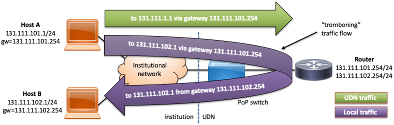
When an institution requires more address space and does not wish to renumber existing hosts, a new address range is often added to a VLAN using a technique called multinetting: this overlays the new addresses on top of the same VLAN by adding secondary addresses to the router interface serving that VLAN. While this avoids having to readdress existing hosts by retaining the ranges used by existing hosts, there are a number of subtle issues presented.
The most obvious issue is that hosts in different subnets using their natural netmask (the one appropriate to the allocated subnet range for that address) won't be aware that they can actually reach each other directly on the same local network and relay traffic through their default gateway, resulting in the packets ricocheting off the upstream router - this is commonly called tromboning or hairpinning for obvious reasons:
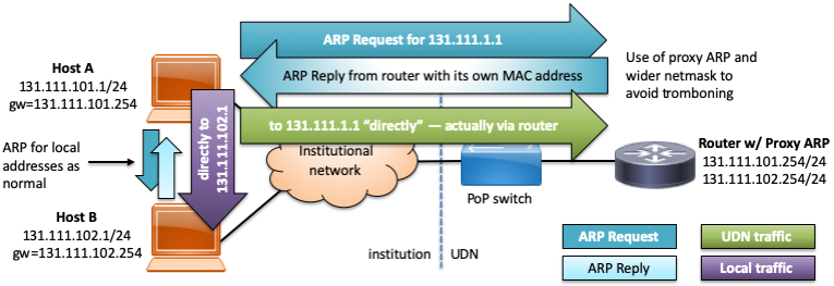
To resolve this, the recommended netmask for subnets on multinetted VLANs routed directly on the UDN is adjusted from the natural/actual netmask to be 255.255.0.0 (/16) and proxy ARP enabled on the UDN router interface. Proxy ARP causes the router to respond with its own MAC address to ARP requests for IP addresses which it can reach and are NOT on the VLAN upon which the request was received. The effect of this is to make hosts believe that the whole of the /16 (either the public 131.111.0.0/16 or private 172.x.0.0/16 blocks) is reachable on the local network but have the router respond on behalf of hosts which are not and route them as normal:
This arrangement results in several potential issues:
- If two hosts in different address ranges have mismatching netmasks configured, the traffic flow between them may be asymmetric, resulting in flooding or performance issues. For example, if host A in the above example had a 255.255.255.0 netmask, traffic from A to B would trombone through the router, but the returning traffic from B (using a netmask of 255.255.0.0.) to A would trombone through the router. Whilst this usually isn't immediately a problem, optimal traffic flow will not be achieved (avoiding tromboning) until all hosts are configured with the wider netmask. Mismatched networks will usually cause problems when a stateful firewall is in use (see below).
- Traffic between ranges outside the recommended netmask range (in particular, between global and UDN-local blocks) will still pass through the router. This is described in more detail in the next section.
- If an institution makes use of institution-local addresses (e.g. 10.0.0.0/17, 172.31.0.0/16 or 192.168.0.0/16 - i.e. NOT UDN-local addresses) on the same VLAN, the proxy ARP responses from the UDN router must be blocked to avoid the router responding on behalf of addresses in these ranges. It is generally more appropriate to create a local institution local VLAN for such devices, which will avoid this issue.
- As the device believes that the whole of the /16 is reachable directly on the local network, it will ARP for any address in this range, potentially building a very large ARP table. For the average client machine, this is generally not an issue as it doesn't talk to a large number of internal hosts; for a server presenting content mainly to clients elsewhere inside the UDN, however, it may be preferable to configure the natural netmask.
Just because the configured netmask is much larger than the natural netmask of the subnet, local subnet broadcast traffic does not get forwarded by the router to other subnets in the same, wider range. For example, when host B above sends a broadcast to 131.111.255.255, this does not get forwarded to all subnets in 131.111.0.0/16.
Traffic between ranges outside the recommended netmask
It should be noted that proxy ARP does not optimise the route between global and UDN-local IP addresses on the same VLAN (unless the netmask was set to an unworkably large range). As such, traffic between global and UDN-local addresses will continue to trombone through the upstream router. If large traffic flows are expected between devices on different types of address, this can be solved in one of three ways:
- renumbering the hosts to all use the same address type,
- using an internal router, or
- adding a secondary address of the other type to certain hosts (e.g. adding a secondary, UDN-local IP address to a server to optimise communication with local clients also on UDN-local IP addresses - the public address may need to be retained if the server needs to be accessible from the internet, e.g. it's an institutional webserver).
Note that adding a secondary address to a server can cause problems with stateful firewalls by creating an asymmetric traffic flow, and typically must not be used, when one is employed. This includes the Managed Firewall Service. For this reason, this solution is no longer recommended and should be removed, where it has been used.
Routed link connection
This connection type is used when an institution has a router or firewall which operates at layer 3 (i.e. routes traffic explicitly, rather than relying on techniques such as proxy ARP). A small link subnet is configured on the VLAN between the UDN router and the institutional router and the IP subnet(s) used by the institution are routed to the IP address(es) used by the institutional router at the end of the link. The institution then takes responsibility for routing the client subnet(s) itself and can configure them however it wishes.
Regardless of the type used, the addresses used on these subnets MUST NOT be used as the outside NAT address or for access control - they are allocated purely to set up the routed link and can change as the UDN is reorganised. If a known global IP address is required, this should come from a range behind the router.
There are two types of routed link; the choice of which to use depends on the complexity of the institution's connection with the UDN:
- Static routed links are used in the vast majority of cases, with a simple, static configuration for their routing: the institution has a single border router (or multiple border routers which redundantly provide the same IP address to the UDN routers) and doesn't need to dynamically update the UDN backbone routing tables, in the event of failover or network reconfiguration.
- Dynamic routed links are generally needed in more complex situations, for institutions with multiple links into the UDN and need to dynamically adjust the routing for their networks, in the event of failover or other reconfiguration.
Proxy ARP is usually disabled on such links as routing will be handled within the institution. Whether an institution uses proxy ARP internally, on their own router(s), is a matter of local preference.
Where the subnets routed over a link include global addresses (exclusively, or in addition to UDN-local addresses), internet best practice is that the addresses used on the link subnet itself should themselves be global, so they appear correctly in traceroutes and other cases where they are exposed (such as ICMP responses). If the subnets used on a link will exclusively use UDN-local addresses, the addresses used on the link can also be UDN-local. The UIS will not route global addresses over a link using UDN-wide addressing, but this does not stop institutions from doing this internally (although it is strongly advised against, similarly if institution-local addresses are used).
Static routed link
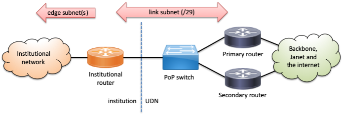
Typically, the link subnet is a /29 providing 6 usable addresses which are divided equally between the institution and the UDN (note that this corresponds to the top scheme used for edge connections, shown above; alternative schemes bottop or bottom may be used for some existing links, to avoid renumbering). For example:
| Subnet base | Owner | Typical use |
|---|---|---|
| + 0 | (reserved) | (base address) |
| + 1 | Institution | Institutional router |
| + 2 | Spare, primary institutional router or device | |
| + 3 | Spare, secondary institutional router or device | |
| + 4 | UDN | Secondary UDN router - physical address |
| + 5 | Primary UDN router - physical address | |
| + 6 | Default gateway to UDN / internet | |
| + 7 | (reserved) | (broadcast address) |
The institution need not configure anything with regards the primary and secondary UDN router physical addresses; they are used internally by the redundant routing configuration and fail over in just the same way as a plain edge connection. The default UDN gateway must be configured on the institution equipment as the default router, otherwise interruptions to service may occur, if one of the routers is unavailable.
An institution can adopt the same redundancy mechanism in reverse, protecting a redundant institutional router address (perhaps on +1) with two physical router addresses on other addresses (+2 and +3). The UDN routes all traffic to the redundant address; if one router fails, the other takes over without the UDN needing reconfigure anything.
In the subnets routed down to the institutional router, all addresses are typically available to the institution in the IP database, with only the base and top addresses reserved for the network and broadcast addresses. If an institution chooses to reorganise the routed space into subnets, there is no requirement to notify the UIS, but the appropriate subnets can be created in the IP database to better reflect the actual organisation and make the netmasks and router addresses for the internal subnets report correctly. This is required to use the DHCP service from UIS Networks, as it needs to understand the internal topology to serve addresses.
Dynamic routed link
This connection type involves the institution running a dynamic routing protocol between their border routers and the UDN routers. The UDN routers will accept routes to institutional subnets via this protocol, allowing the institution to dynamically adjust the routing to their subnets. Where an institution has multiple connections (for example, through multiple PoP switches), the address range on each will be different and the active path(s) controlled by the institution through their use of routing advertisements.
No first hop redundancy is implemented on dynamic routed links as redundancy and failover will be handled as an intrinsic part of the dynamic routing protocol.
Dynamic routed link services to institutions are provided by the UDN BGP Service.
Redundant connections
For resilience against physical cabling and equipment faults, all PoP switches are connected to two separate upstream UDN routers via physically diverse cable paths, as far as possible. In the event of a failure of either of these links (or faults elsewhere on the UDN), the routers should detect this and cause traffic to divert via the remaining usable link:
- Inbound redundancy – protects the first hop (default router / gateway address) used by client hosts for upstream traffic.
- Outbound redundancy – provided multiple paths into an institution (from the UDN out into an institution) for downstream traffic.
These are described below.
Inbound redundancy via first hop (gateway) redundancy
When sending traffic in to the UDN from an institutional network, hosts (or the router on a static routed link) will send it to a single default router / gateway address. To improve resilience against the failure of a single router, the UDN provides a First Hop Redundancy Protocol (FHRP) on institutional network connections. In contrast to the more complex protocols used on the UDN backbone, first hop redundancy does not require any special configuration of client hosts and the failure of a router should only result in an outage of a few seconds (around 3-5).
The actual protocol used to implement first hop redundancy on the UDN may change over time, depending on the manufacturer, model and configuration of routing equipment used. However, the basic principle of all such protocols is the same: the routers providing the redundancy cooperate to offer a single default router / gateway address with a virtual MAC/ethernet address; in the event of failure of the currently active router, a backup takes over the IP and MAC address within a few seconds meaning the clients do not need to make any adjustments to their configuration. The only device which will tend to notice the changeover, aside from the routers themselves, is the PoP switch, which will see the MAC address of the default gateway move from one uplink port to the other.
Examples of FHRPs include the standards-based VRRP (Virtual Router Redundancy Protocol) and proprietary protocols such as Cisco's HSRP (Hot Standby Router Protocol) and GLBP (Gateway Load Balancing Protocol).
This facility is largely transparent but it should be noted that:
- The routers will frequently (every second or so) emit status announcements to indicate they are operating: if they stop, the other router(s) will detect that one has failed and take appropriate action. These announcements are typically made using multicast.
- Traffic from a host to the UDN router will go to the virtual MAC address described above. Traffic from the UDN router to a host will, however, typically come from the real (burnt in / physical) address of the router emitting it.
- The address of the first hop router that shows up in a traceroute can be the redundant address or one of the physical addresses of the upstream routers. Which appears depends on the network equipment in use on the UDN.
- The active first hop router can change to a different one if the upstream UDN router loses or has degraded connectivity to the rest of the UDN, even it is still otherwise functioning.
- In the future, it is possible that a load-sharing protocol will be introduce that provides different gateways to different hosts, perhaps using different MAC addresses.
Because of these reasons, care should be taken, particularly when applying filters to inbound traffic from the UDN. Some firewalls may also have issues if the return path for traffic doesn't exactly match the outbound path.
Group numbers for redundancy protocols
Most FHRPs have some form of group ID which is used to differentiate between multiple instances of the same protocol operating on the same network. In addition, the group ID tends to be used to construct the virtual MAC address. As such, the group IDs must be unique for each group of addresses being managed by a FHRP (a group is typically a set of addresses which all move between routers as they move from a standby to active state). Some institutions may use FHRPs to protect internal services, or their router's outside address on a link subnet with the UDN; the group IDs chosen by the institution for these must not clash with the ID used by the UDN, if that network is routed by the UDN routers.
The range of group IDs varies for each protocol, but are typically an 8- or 12-bit number. To avoid clashes between groups IDs used by the UDN routers and institutional routers, ranges of these numbers are allocated for different purposes (rather like VLAN numbers):
| Group ID range | Status | Use |
|---|---|---|
| 0 - 15 | Reserved | Unused on the UDN (in case of accidental configuration by either party). |
| 16 - 127 | Global | Available for use by the UDN. |
| 128 - 255 | Local | Available for use by institutions. |
| 256 - 2047 | Global | Available for use by the UDN. |
| 2048 - 4095 | Local | Available for use by institutions. |
| 4096+ | Reserved | All other numbers are reserved. |
Typically, group numbers need only be unique on a particular VLAN, so can (and are, on the UDN) reused across VLANs. It is, however, always good practice to select a number conforming with the above range, even if a VLAN is not directly connected to the UDN, as routing may be changed in future.
Outbound redundancy
As stated above, each institutional network is connected to two upstream UDN routers. When sending traffic out onto an institutional network from the UDN, traffic can come from either of these two routers, not necessarily just the one which is providing the currently active default router / gateway.
The UDN employs equal-cost multipath routing (ECMP), whereby traffic is shared amongst the available best paths across the backbone, including both downlinks to the PoP, not just a single active one. This increases the effective bandwidth into a particular site and better utilises the available capacity of the backbone and downlinks. This theoretical doubling is not part of the guaranteed service, however.
It should be noted that:
- Traffic between any particular pair of hosts (a single source-destination pair) should always take the same path (unless a routing topology change causes this to be recalculated).
- If traffic is distributed perfectly, it could theoretically result in an effective downstream bandwidth increase to use all available links (e.g. if a PoP switch has 2x 10Gbit/s connections to the routers, it is technically possible to get 20Gbit/s of downstream bandwidth). It is more likely that speeds somewhere between that of one link and both links will be achieved (i.e. between 10Gbit/s and 20Gbit/s, for the above example PoP), however.
- Multipath has no effect on upstream bandwidth: that will still all go via a single uplink. Work may be done in future to better distribute traffic across the two links.
- Because of blocks to prevent the spoofing of source addresses, it may be the case that neither, one or both of the physical subnet addresses of the routers will be unreachable from elsewhere on the UDN (returning an 'administratively prohibited' ICMP error from the target router); the redundant gateway address itself may or may not be reachable. Which routers (and the gateway) are reachable at any point can vary over time (although usually only as a result of topology changes). From a host on the client subnet, there will be no trouble reaching either router, however - this situation is normal and should be ignored: connectivity to the hosts themselves on the subnet will work without issues.
The last issue is important as the failure of a ping to the gateway address at another site may not indicate there is a problem with that site. If a way is required to monitor the status of the link from another location, the institution will need to monitor a "reliable" host — something which is likely to be online at all required times: perhaps a server or other dedicated host.
Services available on edge connections
In addition to regular IP routing, there are a number of services which can be enabled on an edge connection.
These services need to operate on the first hop router for a particular connection: if an institution has a routed link connection, these should be implemented on the institution internal router(s).
DHCP relaying
If an institution wishes to use DHCP to configure client hosts on a particular connection, with servers located elsewhere on the UDN (on a different VLAN), the first hop routers serving the clients can be configured to relay the DHCP messages between the clients and servers.
To configure this service, the IP address(es) of the DHCP servers will need to be supplied, along with the details of the client network to be served (typically by giving one of the IP ranges in use on that connection).
There are several things to note about this service, as used on the UDN:
- DHCP relaying is configured on a per-VLAN, not a per-subnet, basis: the routers do not know to which subnet a host will eventually belong, until the DHCP process has completed. This is important if multinetting is in use on a VLAN.
- The relaying routers will record their physical interface addresses in the gateway IP address field of the DHCP packet, when they forward it on. This allows the DHCP server to know which VLAN the request originated on.
- If multinetting is in use, the gateway IP address could be in any of the configured ranges (although will typically be the primary IP range, so should be consistent, unless this is changed through necessity). The DHCP server should be configured with all ranges in use as a shared network.
- Because of the first hop redundancy protocol configuration on the UDN, DHCP servers will typically receive two copies of each request (one via each router).
No configuration is required if the DHCP server is located on the same VLAN as the clients: they will see the request via local broadcast.
UIS Networks offer a DHCP service linked to the IP management database and it is recommended that institutions use this, where possible.
Directed broadcast forwarding (for Wake-on-LAN)
Similarly to DHCP relaying, if an institution wishes to make use of directed broadcast across VLANs, this can be enabled. The most common use for this is to allow a Wake-on-LAN magic packet to be sent from a server to a client.
Directed broadcasts are normally disabled due to their potentially disruptive nature (if a rogue hosts transmits data to the directed broadcast address, this can generate significant traffic on the target network). To restrict what data is forwarded as a directed broadcast, this is typically enabled with an access list specifying:
- The source address(es) of the packets (who can send the directed broadcast).
- The destination port(s). For magic packets, UDP port 9 (discard) is often used, as it should have no effect on a host which is awake.
Institutions should state the target network to enabled for directed broadcasts (either by VLAN ID or IP range), along with the above restriction information.
Multicast forwarding
If multicast services are required on an edge subnet, these can be enabled. This process is described on the multicast page.
Hostnames for router addresses
Because the IP addresses used for the routers are held by different routers at different times, depending on failover status, it doesn't make sense for the names of the gateway/router addresses to reflect the actual routers they are assigned to.
As such the router addresses are registered with names such as the following (where <id> is usually a number corresponding to the VLAN ID for this subnet):
gw-<id>.net[.private].cam.ac.uk- for the default router / gateway (e.g.gw-789.net.cam.ac.ukfor VLAN 789)gw-<id>.d-<router-short-code>.net[.private].cam.ac.uk- for each of the primary and secondary routers (e.g.gw-789.d-nm.net.cam.ac.ukfor the VLAN 789 interface on dist-nms).
Note that these names may resolve into multiple addresses, if the VLAN is multinetted.
The short codes for routers are the first characters of the full name of the router (e.g. "d-nm" is short for dist-nms). This, along with shortening "dist" to "d" just shortens the names to use up less screen width in outputs (which is especially important when router names are used at both ends, in a backbone link on the network).
Many names were created prior to this scheme and have either the full names of the routers, or the previous names for the routers in their name, in the form gw-<id>[.route-<router-name>].net[.private].cam.ac.uk. These will be adjusted, in due course.
Last updated: 9th May 2024