The UDN MPLS Virtual Private Network (MPLS VPN) service allows internal parts of institutional networks to be routed across the UDN infrastructure, keeping them separate from the global UDN traffic, except where explicitly interconnected.
At client sites, the MPLS VPN is presented as a regular VLAN, which can be fed from the PoP switch to where it is required. This enables an institution to extend its internal network to other sites without needing to rent additional fibre capacity or operate its own network of routers, whilst benefiting from the redundancy, resilience, capacity and physical reach provided by the existing UDN infrastructure.
For institutions that have been asked to host part of the internal network of others typically just need to carry this additional VLAN from their PoP to the required hosts.
The MPLS VPN service is provided using MPLS (Multi-Protocol Label Switching) technology on the backbone equipment. The exact operation of MPLS is beyond the scope of this documentation. Unlike with BGP, however, it is usually unnecessary for institutions to understand, configure or support this protocol to use the MPLS VPN service: the UDN routers provide the translation between regular (non-MPLS) IP routing protocols and MPLS forwarding used on the backbone, although a technical introduction to MPLS VPN is provided, for those interested.
This service only supports layer 3 (routed) connections between sites. For layer 2 (switched) VLAN services between sites, the UDN provides the inter-site VLAN service.
Important note: this service should not be confused with the UDN Remote Access VPN service, which is used by end users wishing to connect into the UDN from elsewhere on the internet. To help reinforce this distinction, the VPN service provided here will be referred to as an 'MPLS VPN'.
Contents
- Introduction to MPLS VPN
- Routing
- Presentation at a site
- Protocol support
- Address space
- Multicast
- Helper services (DHCP and directed broadcast forwarding)
- Traceroutes
- Security of traffic
- Management of routers
- Prices
- Technical introduction to MPLS
Introduction to MPLS VPN
The simplest way to think of an MPLS VPN is as a completely separate set of routers, each with their own routing tables (default routes, connected VLAN interfaces, etc.). These routers are usually set up to route traffic for (part of) the internal network of an institution.
For example, ignoring redundancy arrangements and other details of the UDN (such as the precise structure of core and distribution routers), consider the following diagram of St. Botolph's College:
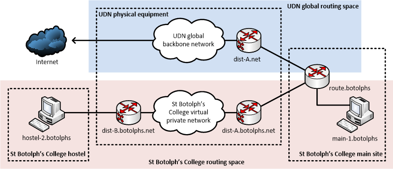
Here:
- dist-A.net is a regular router, outside of the College network and routes traffic across the UDN global address space, between institutions and out onto the internet; it also routes traffic into St. Botolph's College's network via route.botolphs.
- route.botolphs is an institutional router that routes traffic between the regular UDN backbone (via route-A.net), a local internal client subnet (with host main-1.botolphs) as well as to an internal backbone network (via dist-A.botolphs.net) to extend to a hostel site.
- dist-A.botolphs.net is a backbone router inside the institutional network: it routes traffic via route.botolphs to the internet (including the global part of the UDN, outside the institution) and the client subnet at the main institution site; it also routes traffic across the backbone network to a router serving a remote site (dist-B.botolphs.net).
- dist-B.botolphs.net is another backbone router inside the institutional network: it is the client subnet router for a hostel site (serving hostel-2.botolphs) and also routes traffic bound for the internet and institution main site back across the backbone to dist-A.botolphs.net.
An MPLS VPN allows the two internal backbone routers, dist-A.botolphs.net and dist-B.botolphs.net to be physically the same routers used for the UDN global address space, but have their own private Virtual Routing and Forwarding (VRF) tables. In the example above, dist-A.net and dist-A.botolphs.net are different logical routers provided by the same physical piece of router hardware, with the two links connecting to route.botolphs being provided as separate VLANs on the same physical link. Each of the logical links have separate IP address ranges.
route.botolphs could also provide a firewall service, filtering traffic between the institutional network (including the MPLS VPN) and the global UDN via single, central institutional firewall. Indeed, this is one of the primary reasons for using an MPLS VPN: forcing traffic for an institution's sites, distributed around the UDN, back through a central firewall.
Of course, in reality on the UDN, these routers are in redundant pairs, with gateway addresses protected by a first hop redundancy protocol. There are also typically PoP switches situated at each site, handling failover of the uplinks to the routers. The institutional network can also be more complicated: the 'outside' and 'inside' links with the UDN can be provided by separate institutional routers.
The service can easily be scaled, with multiple remote sites being served from the same or separate routers. Typically, when multiple remote sites are added, traffic routes directly between them (over the MPLS VPN), without hubbing back via the main site.
Routing
Routing to and from an MPLS VPN (between an institutional network and the 'inside' router provided by the UDN) can use either static or dynamic routing:
- Static routing is ideal for simple cases, with a single 'main' site acting as a gateway in and out of the network.
- Dynamic routing is useful in more complex cases and can support multiple, redundant gateways between the MPLS VPN and the institutional network, potentially at different sites. This configuration requires a good understanding of BGP to implement.
These cases can also be mixed (with some connections into an MPLS VPN being static and some being dynamic), as long as they do not create a conflict between static and dynamic routing information.
Static routing
Where an institution has a single 'main' site, with a single router providing the gateway between the MPLS VPN and the institutional network, a simple static routing configuration is the easiest the configure. Redundancy is limited to that provided by protecting the gateways at each end of the link with a first hop redundancy protocol (which can include the institutional router).
For example, consider the following setup for St. Botolph's College (considering only IPv4; IPv6 is fully supported but will obviously use different addresses on each connection):
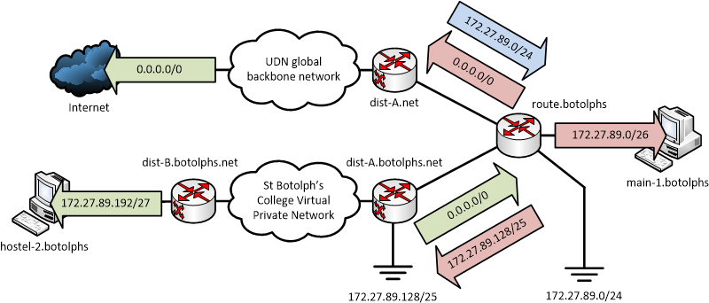
The ranges in use are as follows:
- 172.27.89.0/24 is allocated to St. Botolph's College on the UDN, this includes:
- 172.27.89.0/26 used on the College's main site
- 172.27.89.128/25 used for connecting College hostels using the MPLS VPN service, of which only 172.27.89.192/27 is currently in use
- An 'outside' /29 link subnet between dist-A.net and route.botolphs (the exact range is unimportant for this example; a /29 is used to support the physical router addresses for a first hop redundancy protocol)
- An 'inside' /29 link subnet between route.botolphs and dist-A.botolphs.net
The routing is then configured as follows:
- On dist-A.net (the global UDN router), the 172.27.89.0/24 range used by the College is routed via the 'outside' address of the College router, route.botolphs.
- route.botolphs has a 'connected' interface serving hosts on the main site (in 172.27.89.0/26); the default route (0.0.0.0/0) is set via the UDN global router (dist-A.net) and the 172.27.89.128/25 range used by the MPLS VPN for hostels is routed back into the UDN via dist-A.botolphs.net, the router inside the MPLS VPN.
- dist-A.botolphs.net is configured with a static default route (0.0.0.0/0) via the 'inside' address of route.botolphs.
- dist-B.botolphs.net has an interface serving the hosts at the host site (172.27.89.192/27).
- Routing information inside the MPLS VPN, between dist-A.botolphs.net and dist-B.botolphs.net, is exchanged using a variety of protocols related to MPLS (including MBGP — Multiprotocol BGP), but this is transparent to the institution.
The above configuration supports an easy expansion of the MPLS VPN service: further sites can be added, using addresses inside the 172.27.89.128/25 range already routed into the MPLS VPN (for example, 172.27.89.224/27). To avoid routing loops, however, some additional blackhole or null routes need to be set up:
- route.botolphs has a blackhole route for 172.27.89.0/24 to match ranges which are not (yet) otherwise routed (by longer prefixes) and avoid traffic to unused addresses bouncing between dist-A.net and route.botolphs (as the latter would otherwise match the default route).
- Similarly, dist-A.botolphs.net has a blackhole route to 172.27.89.128/25 to match unused ranges inside the MPLS VPN, rather than having traffic bouncing between it and route.botolphs.
An institution requesting the MPLS VPN service should produce a diagram similar to that above, to explain the desired configuration. This should show the PoP switches and subnets involved.
As a network becomes more complicated, it may be desirable to move to a dynamic routing configuration. An MPLS VPN can initially be set up with static routing and then transitioned to dynamic routing, if needs arise.
Dynamic routing (BGP)
To provide more redundancy on the connection between an MPLS VPN and an institutional network, BGP can be used to allow multiple, independently-routed links, potentially split across different sites. The operation of this is almost identical to one outside of an MPLS VPN, in the UDN global address space: eBGP peerings are established on the 'inside' connection between an institution's router(s) and the UDN ingress routers to the MPLS VPN and the routes exchanged. In this case, however, the institutional network is effectively the upstream provider to the MPLS VPN (offering the gateway out onto the UDN and internet).
The configuration is commonly known as MPLS Inter AS Option A or VRF Lite, contrasted with Option B, below.
The use of eBGP on the 'inside' links is usually combined with eBGP peerings outside the MPLS VPN, to provide equivalent redundancy on the 'outside' connections between the institutional routers and the UDN global address space routers.
For example, consider an expansion of the St. Botolph's College network to include BGP on both the 'outside' and 'inside' connections:
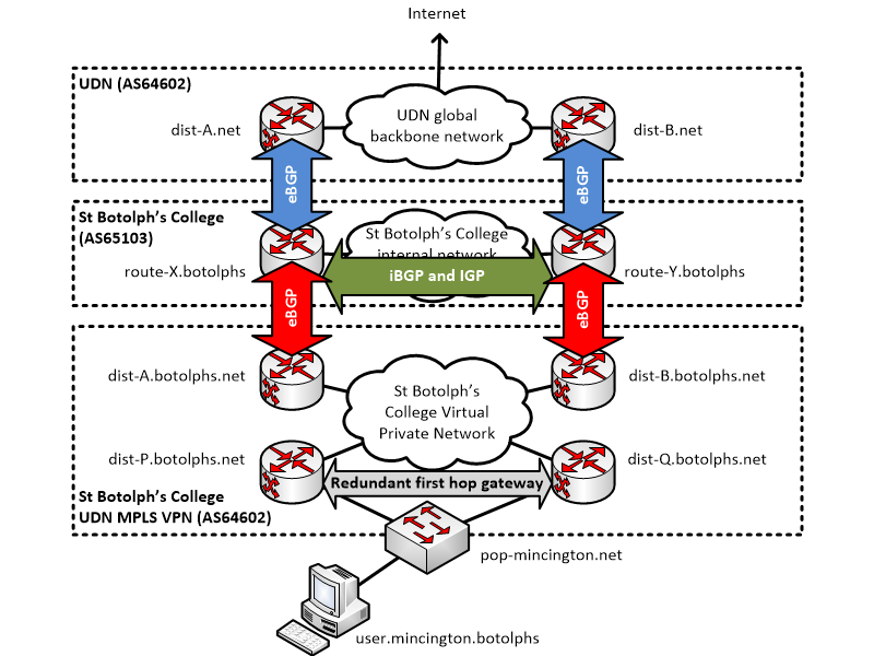
Here:
- The pairs dist-A.net / route-X.botolphs and dist-B.net / route-Y.botolphs have normal eBGP peerings, outside the MPLS VPN. These, along with an internal St. Botolph's College network, provide a redundant connection between to the global UDN and the College network. The UDN routers advertise the UDN prefixes and default route; the College routers advertise the College prefixes.
- To provide redundancy linking into the MPLS VPN, the pairs route-X.botolphs / dist-A.botolphs.net and route-Y.botolphs / dist-B.botolphs.net also have eBGP peerings. Here, the roles are reversed: the College routers provide the upstream connectivity, advertising the College and UDN prefixes and default route; the UDN routers inside the MPLS VPN advertise either a summary prefix (covering all ranges used inside the MPLS VPN) or the prefixes of individual sites.
- The institution must run the appropriate iBGP peerings and IGP (Interior Gateway Protocol) to handle redundancy across their internal network.
Remote (client) sites can be connected via a VLAN to a regular UDN PoP switch and routed directly by the UDN routers, as with a static configuration. The example above shows a St. Botolph's College user hosted at Mincington College: the St. Botolph's College user is placed on the "St. Botolph's College users in Mincington College" client VLAN and will be routed back across the MPLS VPN, through to the St. Botolph's College internal network and then out onto the global UDN.
The following should be noted about the 'inside' peering:
- The AS number of the UDN routers inside the MPLS VPN will be the same as that in the global space: 64602.
- There will be separate /30 'inside' link subnets from the 'outside' link subnets (in the above example, there will be four link subnets: dist-A.net / route-X.botolphs and dist-B.net / route-Y.botolphs, outside the MPLS VPN, and route-X.botolphs / dist-A.botolphs.net and route-Y.botolphs / dist-B.botolphs.net inside the MPLS VPN).
- As with a static configuration, the institutional network can be more complicated than shown: the 'inside' peering does not need to be with the same institutional routers as the 'outside' peering.
- Although the AS number is the same, the policies an institution should implement on the peering will be different:
- The institutional network will need to advertise routes to their internal network (probably by redistributing their blackhole routes) as well as to the UDN prefixes and default route. This is because the MPLS VPN will need to use the institutional network to reach external routes.
- The institutional network will need to accept routes over the peering for sites inside the MPLS VPN.
- If an institution wishes to re-advertise routes learnt from the global UDN into the MPLS VPN, the eBGP peerings into the MPLS VPN will need to be configured to accept a route with their own ASN (AS Number) as part of the path (since they would otherwise reject it). The institution should make it clear this is required.
- To maintain maximum flexibility and ease of management, the filtering of routes into and out of the MPLS VPN may not be as strict as a global UDN peering: as the network is contained within an institution, it is the responsibility of that institution to ensure that the correct routes are accepted and advertised.
- As with any BGP peering, it is recommended that route summaries be used where possible, to minimise the number of routes exchanged.
As with a static configuration, an institution requesting the MPLS VPN service must produce a diagram showing the routers involved, along with the subnets and client sites.
Dynamic routing (BGP with MPLS)
As an alternative to the above, regular BGP configuration, the UDN supports direct MPLS forwarding between ASs, avoiding the need to create the separate internal BGP peerings and link subnets. Instead, the existing "outside" BGP peerings are used to exchange MPLS VPN routing information between the UDN and the institution and labeled packets exchanged between them.
This configuration is known as MPLS Inter AS Option B (the above configuration is known as Option A) and requires that the institutional network border routers support MPLS.
The configuration involves:
- The institution should select some MPLS Route Distinguishers (RDs) using the type 1 format, with the IP address part being a UDN-routed address belonging to the institution and an assigned number of their choice.
- The institution will be advised of the appropriate Route Targets (RTs) to use for the VPN routes.
- The existing external BGP peering with the UDN will have the VPNv4 (and VPNv6, if IPv6 is used) address-families added to it.
- The MTU used across the links with the UDN will be increased appropriately, to accommodate the MPLS labels.
- MPLS forwarding will be enabled across the existing external links to the institutional network.
This configuration is relatively advanced and the institution will need to ensure they have a good understanding of the required configuration and protocols. It is generally only desirable when an institution has a large number of MPLS VPNs as it simplifies the configuration of these, avoid multiple internal link subnets. For simple configurations, the internal BGP peering mechanism is probably more appropriate.
Presentation at a site
The way an MPLS VPN is presented on a particular connection varies according to the method used to connect the UDN at that site, namely whether a PoP switch or a directly-routed link is present.
These methods can be mixed within a particular MPLS VPN. For example, a main site may use routed links but the remote sites may use VLANs fed through a PoP.
Connection via a PoP
If a site has a PoP switch, an MPLS VPN connection is presented as a single VLAN, with the two UDN routers serving that PoP being set up in a redundant pair using a first hop redundancy protocol. The institution will see the VLAN as any other and can feed it through their network as required.
This technique is particularly useful when one institution wishes to have part of their internal network fed into another, allowing the two networks to be kept logically separate. This requires that the hosting institution merely add an additional VLAN to their internal network, similar to a voice client or wireless access point management network, and feed it through to where it is required by the client institution. The responsibility for the traffic on the hosted network is the responsibility of that institution (rather than the hosting institution), in terms of charging, IP allocation and CERT responsibilities.
As with any VLAN fed to the PoP, the institution should confirm how they would like it presented (which ports and how: tagged or untagged; edge ports or trunk ports).
It is also possible to have an MPLS VPN presented in the same manner as a directly-routed link, though multiple VLANs (one per inter-router link) on the PoP. This is the same as when BGP is used through a PoP.
Connection via directly-routed links
If an institution does not have a PoP (and thus uses a dynamic routed connection with BGP for their global connection), routed VLANs with first hop redundancy cannot be provided across the point-to-point links between the institutional border routers and the UDN routers. In this case, it is necessary to interface with the MPLS VPN through eBGP peerings.
However, the 'inside' and 'outside' links can be presented as different VLANs on the same physical connection. In the dynamic routing configuration above, the route-A.net / route-X.botolphs and route-X.botolphs / route-A.botolphs.net links would use the same physical fibre; the other link (route-B.net / route-Y.botolphs / route-B.botolphs.net) would use another.
Protocol support
The MPLS VPN service supports a subset of protocols available in the UDN's global address space:
- IPv4 — unicast and multicast
- IPv6 — unicast only
Support for each protocol must be explicitly enabled: institutions will need to state which are required.
Address space
The address space used inside the MPLS VPN is that of the internal network of an institution. This is likely to involve one or more of:
- public (globally-routable) addresses (e.g. 131.111.x.x, or 2001:630:21x:...),
- UDN-wide private addresses (e.g. 172.16.x.x) which will be SNATed (Source Network Address Translated) at the border of the UDN, before exiting onto Janet / the internet, and
- institution-private addresses (e.g. 192.168.x.x)
Although institution-private addresses can be routed around inside the MPLS VPN, they cannot be routed directly onto the global portion of the UDN (through an institutional router), without first being translated (with SNAT) into either UDN-wide or public addresses (for internet-bound traffic, it is best to use public addresses to avoid double NAT).
The UDN itself cannot provide this translation service: this must be implemented by an institution (most likely at their 'main' site). If outbound external connectivity (either to the public internet, or just to the UDN) is required from an MPLS VPN, it is recommended to use UDN-wide private addresses for hosts on the internal network: this has the advantage of simplifying the networking at the institution (by eliminating the need for the institution to run an SNAT service, along with associated logging) and allowing the real addresses of hosts on an internal institutional network to be seen, making tracing easier (and allowing individual internal hosts to be blocked or examined).
The institution is free to advise UIS as to which addresses/subnets are to be routed where, as required by their internal networking policy. However, for administrative reasons, the UDN cannot currently route ranges overlapping public and UDN-wide private ranges in a manner contradictory to the UDN global allocation policy. For example, an institution cannot request that the range of another institution is routed internally (e.g. St. Botolph's College cannot ask for a UDN-wide private subnet of the Department of Small Studies to be routed to one of their hostels, unless it really is part of the Department of Small Studies). Institution-private addresses can be routed without restriction.
Router addresses
When routing client subnets, the addresses chosen for the routers must typically follow one of the UDN edge schemes.
For IPv4, the recommended scheme is 'top' (whereby the router address is 'top - 1' [one less than the broadcast address] and the two addresses below this are used for the routers' physical addresses, to managing the first hop redundancy protocol).
For IPv6, a fixed router address is normally provided at subnet::1, as per a global UDN connection. However, most hosts will discover the router through ICMPv6 RA (Router Advertisement).
Hostnames
Registration of the addresses used by hosts inside an MPLS VPN depends on the type(s) of addresses in use:
- For UDN global addresses, the hosts can be registered in the IP Register database, as normal. The subnets and UDN router addresses will be automatically registered, when the MPLS VPN is set up.
- If institution private addresses are used, it is the responsibility of the institution to register and reserve the addresses used by the UDN routers in their own local registry.
When registered in the DNS, the names for the UDN routers inside the MPLS VPN will typically have an additional institutional element added below the 'net', to indicate the institution to which the MPLS VPN applies.
For example, in the St. Botolph's College example above, the client subnet 172.27.89.192/27 is fed to a hostel. Assuming this is presented to the hosting institution (Mincington College) as VLAN 788, and the UDN routers providing the gateway are route-B (the primary) and route-C (the secondary), the addresses will be registered in IP Register as follows:
- 172.27.89.220 — gw-788.dist-C.botolphs.net.private.cam.ac.uk (note the extra 'botolphs' under 'net')
- 172.27.89.221 — gw-788.dist-B.botolphs.net.private.cam.ac.uk
- 172.27.89.222 — gw-788.botolphs.net.private.cam.ac.uk (the gateway address protected by first hop redundancy, which should be used by clients)
- 172.27.89.{193-219} — available for an institution to register client hosts (probably directly in the botolphs.net.private.cam.ac.uk; whether an the site is indicated in the hostname through an extra layer in the DNS path, or with a prefix, is up to the institution)
Multicast
At the present time, only IPv4 multicast is supported inside an MPLS VPN. IPv6 multicast may be supported in the future, when technology and equipment allow.
Multicast inside an MPLS VPN requires careful configuration to support it in a scalable manner. Institutions requesting multicast must discuss with UIS Networks how they plan to use it so it can be configured correctly. Details required include:
- the locations and numbers of sources and members
- the number and bandwidth of simultaneously active groups
- the frequency and times when multicast will be used
A less optimal configuration will still work, but may not give best performance, or be the most efficient, in terms of the resources used on network links and router processing.
Configuration of the 'outside' and 'inside' connections to the UDN are different:
- On the outside link to the UDN, the normal inter-domain configuration is required, comprising PIM-SM (Protocol Independent Multicast – Sparse Mode), BGP RPF (Reverse Path Forwarding) routes and MSDP. The institution must also provide its own PIM-SM RP (Rendezvous Point).
- However, the whole of the inside of the institutional network (comprising both the institutional network and the MPLS VPN) is a single PIM domain: a PIM-SM RP should be configured inside the institutional network and advertised to the UDN routers across the 'inside' connection using PIM BSR (BootStrap Router) protocol; this RP will likely be the same one as set up for the outside connection.
This is illustrated by the following diagram:
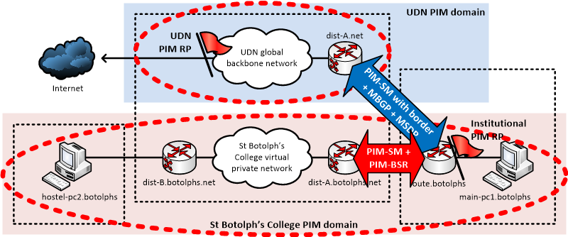
If an institution only requires that multicast works internally (and not be connected to the global UDN), only the 'inside' part of the configuration needs to be set up.
Helper services (DHCP and directed broadcast forwarding)
The DHCP relay and directed broadcast (typically to support Wake-on-LAN) services are available on subnets routed inside an MPLS VPN, just as they are on subnets in the global address space. The packets will be relayed within the MPLS VPN (and back through the institutional router(s) onto the global address space, if appropriate).
Traceroutes
Traceroutes across an MPLS VPN provided by the UDN will not expose the individual backbone routers traversed to reach each site; only the ingress UDN router into the MPLS VPN will be shown.
For example, consider the following traceroute from the global address space to inside an MPLS VPN for the University Library:
kikuchiyo:~ rcf34$ traceroute 172.22.84.9
traceroute to 172.22.84.9 (172.22.84.9), 64 hops max, 52 byte packets
1 gw-480.route-ucs-rnb.net.cam.ac.uk (131.111.57.253) 0.971 ms 0.744 ms 3.159 ms
2 ucs-rnb.d-mw.net.cam.ac.uk (193.60.95.125) 3.520 ms 13.186 ms 1.174 ms
3 d-mw.c-ce.net.cam.ac.uk (131.111.6.53) 0.458 ms 0.368 ms 0.364 ms
4 c-ce.d-si.net.cam.ac.uk (131.111.6.6) 0.512 ms 0.455 ms 0.452 ms
5 router01.ds.lib.cam.ac.uk (193.60.91.153) 0.385 ms 0.394 ms 0.427 ms
6 link.d-si.lib.net.cam.ac.uk (193.60.90.242) 0.621 ms 0.607 ms 0.596 ms
7 moore-pc9.lib.private.cam.ac.uk (172.22.84.9) 1.681 ms 1.638 ms 1.660 ms
The various hops are:
- Hop 1 is the first hop institutional router of the traceroute source.
- Hops 2 to 4 are traversing the UDN backbone global routing space to get to the border router into the University Library.
- Hop 5 is the University Library border router / firewall.
- Hop 6 is the ingress router, feeding into the MPLS VPN provided the UDN (note the domain ending 'lib.net.cam.ac.uk' to indicate the University Library MPLS VPN hosted on the UDN).
- Hop 7 is the traceroute target device itself.
Note that the intermediate UDN backbone routers inside the MPLS VPN are not shown between hops 6 and 7 (in particular, the UDN router serving the target device).
In the reverse direction (from inside the MPLS VPN to the global address space), only the ingress router at the remote site is shown:
C:\>tracert 131.111.56.1

Tracing route to kikuchiyo.csi.cam.ac.uk [131.111.56.1]
over a maximum of 30 hops:

1    <1 ms    <1 ms    <1 ms  gw-411.d-we.lib.net.private.cam.ac.uk [172.22.84.61]
2    <1 ms    <1 ms    <1 ms  inside-router.lib.cam.ac.uk [193.60.90.246]
3     1 ms     1 ms     1 ms  gw-246.d-si.net.cam.ac.uk [131.111.164.254]
4     1 ms     1 ms     1 ms  d-si.c-ce.net.cam.ac.uk [131.111.6.5]
5     1 ms     1 ms     1 ms  c-ce.d-we.net.cam.ac.uk [131.111.6.14]
6     1 ms     2 ms     4 ms  d-we.ucs-rnb.net.cam.ac.uk [193.60.95.122]
7     1 ms     1 ms     1 ms  kikuchiyo.csi.cam.ac.uk [131.111.56.1]

Trace complete.
In this direction:
- Hop 1 is the first hop UDN router at the remote site inside the MPLS VPN.
- Hop 2 is the University Library router / firewall which connects to the inside of the MPLS VPN.
- Hop 3 is the UDN router linked to the outside of the University Library router / firewall in the global routing space.
- Hops 4 and 5 are the UDN backbone global routing space.
- Hop 6 is the institutional router at the target end.
- Hop 7 is the host itself.
Again, note that the intermediate UDN backbone routers inside the MPLS VPN are not shown between hops 1 and 2. Also note that, in the example above, hops 1 and 5 are the same physical router, as the packet passes through twice, on the inside of the VPN (hop 1) and the outside (hop 5).
Security of traffic
It should be noted that, unlike a remote access VPN, traffic across an MPLS VPN is not implicitly secured with encryption or authentication, beyond the separation from global traffic provided by the operation of the protocol itself.
Institutions requiring additional security should use IPSec, SSL or other techniques for encrypting and/or authenticating data. Whilst every care is taken to keep the MPLS VPN traffic private, it is possible a configuration error or operational problem may cause traffic to leak into or out of an MPLS VPN onto the global network.
The UDN and UIS Networks are not responsible for any issues that occur due to such problems.
Management of routers
Although the UDN routers inside an MPLS VPN are effectively providing part of an institution's internal network, they are still managed by UIS Networks: no special access to query or reconfigure them is provided, as per normal, global UDN routers. This includes SSH/TELNET and SNMP.
At some point, it is hoped to offer some visibility into the network, such as a Looking Glass to query routes, or an API to query ARP tables.
Prices
The MPLS VPN service is charged-for, on a per-site basis, to the "home" institution (the one requesting the private network; not necessarily the one where the VLAN is presented):
|
Annual Charge |
New Installation |
|
| MPLS VPN as an additional routed VLAN via PoP | £74 | - |
| MPLS VPN as an pair of eBGP peerings | £74 | - |
All prices are subject to VAT, where applicable.
A "site" is considered to be either:
- A redundantly-routed VLAN presented on a PoP (either the institution's home PoP, or another PoP), or
- A pair (or part, thereof) of eBGP peerings inside the private network — typically two are required into a single AS.
For example, in the diagram shown in the introduction, St Botolph's College would pay for two site charges: one for the private link inside their network (between route.botolphs and dist-A.botolphs.net) and one for the VLAN presented on the PoP serving the remote hostel (from dist-B.botolphs.net).
An institution may request that the main data VLAN presented on a PoP is inside an existing MPLS VPN (e.g. if the PoP is installed for that institution and is an extension of their internal network) for no extra charge as it is the VLAN included in that service.
Technical introduction to MPLS
Note: This section is intended as a basic introduction to how MPLS operates — it is not necessary to understand this to utilise the MPLS VPN service described here. For a more complete technical introduction, please see a guide such as MPLS Fundamentals by Luc De Ghein, published by Cisco Press.
MPLS (Multi Protocol Label Switching) works by prefixing packets traversing the provider network (in this case, the UDN) with one or more labels. These labels are used in place of the normal forwarding methods based on MAC address (switching) and IP address (routing).
As a packet enters the MPLS VPN from a customer (institutional) network, the ingress router of the provider network prefixes the labels required for the packet to reach the required egress router. On the egress router, these labels are stripped off, restoring the original packet for forwarding on to its destination, back into the customer network at another site. The ingress and egress routers are known as Provider Edge (PE) routers.
The labels are arranged such that only the PE routers need to know about the MPLS VPN itself: the routers in between need only understand the label stating which router is the egress router, not what the traffic being carried actually is (or even what MPLS VPN it is part of). The routers in the middle of the network are known as the Provider (P) routers.
This arrangement simplifies deployment, as only the PE routers need to be explicitly configured with the details of an MPLS VPN: the P routers only need to know enough to carry traffic between one PE router and another. This enables MPLS to scale well, as the P routers do not need to have knowledge of the routing tables of the customer networks.
Indeed, it is possible for the P routers to route traffic other than that which they are normally capable of forwarding (for example, IPX). This is the Multi Protocol nature of MPLS: only the PE routers need to understand the traffic being forwarded and how to add and remove the labels as it enters and exits the MPLS network.
A series of protocols are used to communicate the meaning of the labels between routers. In particular, MBGP (Multiprotocol BGP) is used to distribute the labels used to identify the different VPNs in use on the network; PE routers can translate between regular (non MPLS VPN) routes and MPLS VPN routes, when relaying them between the customer routers and other PE routers.
Last updated: 3rd November 2020